
1. Presentation of synchronous machines
1.1 Construction
Synchronous machines are made up of two parts:
- Rotor
This is the rotating part. For small machines, it is made of a permanent magnet; but in general, it is an electromagnet in the form of a massive ferromagnetic cylinder receiving a winding which, supplied with direct current (excitation), generates p pairs of alternating south and north poles.
There are rotors with salient poles with a high number of pole pairs p or with cylindrical poles. Figure 1 geometrically represents the difference between both rotor types.
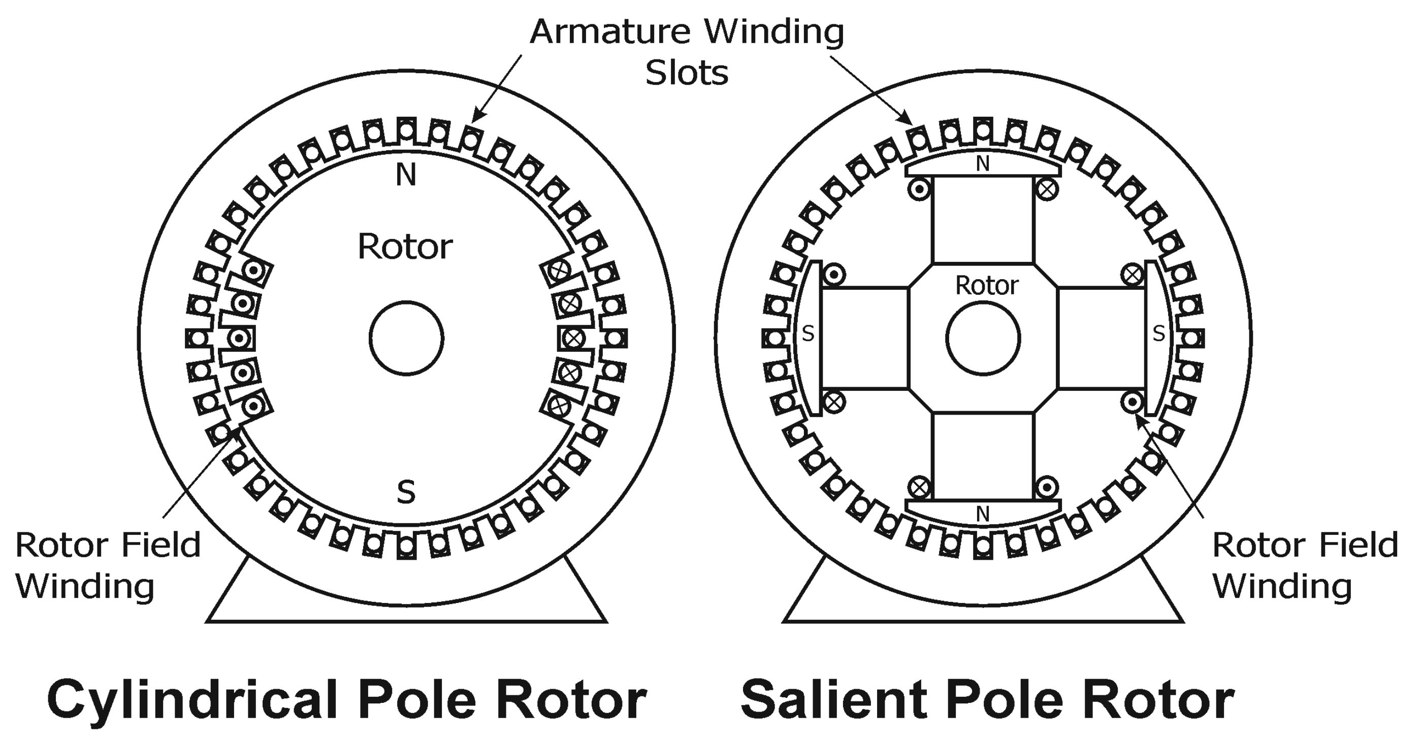
Figure 1: Rotor Types of Synchronous Machines
In the case of synchronous machines, the rotor is considered as the inductor and the armature is the stator.
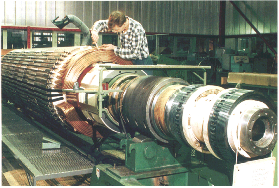
Figure 2: Rotor of a cylindrical poles synchronous machine
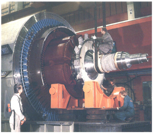
Figure 3 : Rotor of a salient pole synchronous machine
- Stator
It is the fixed part, in the form of a laminated ferromagnetic carcass with a three-phase winding which, traversed by balanced three-phase currents, generates a rotating field with quasi-sinusoidal distribution with the same number of poles as the rotor. The windings can be coupled in star (most common case) or in triangle.
1.2 Working principle
If the rotor is driven at the constant speed Ω, the stator windings in contact with the rotor rotating magnetic field, create by induction a three-phase system of angular frequency ω = p. Ω or f = p. n (ω and Ω in rad/s, speed n in rev/s and p: the number of pairs of poles of the rotor). This is the operating principle of an alternator used in the production of electrical energy.
1.3 Reversibility
For motor operation mode, the stator is supplied by a three-phase system and the rotor is started, which continues to rotate at the synchronous speed Ω = ω/p of the rotating magnetic field (this rotating field represents both stator and rotor rotating fields).
1.4 Excitation of the machine
The excitation may be of two types:
- an external source which supplies the rotor with direct current through a system of brushes and rings.
- or the machine itself provides its own excitation via an exciter generator or an auxiliary alternator connected to the shaft. We then say that the machine is self-excited.
1.5 Symbols and convention
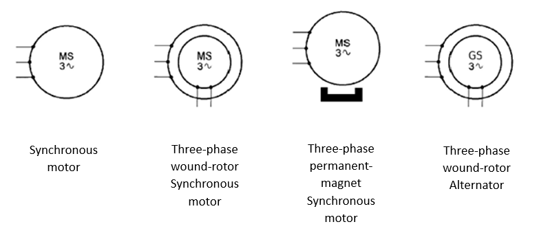
Figure 4: Symbols of three-phase synchronous machines
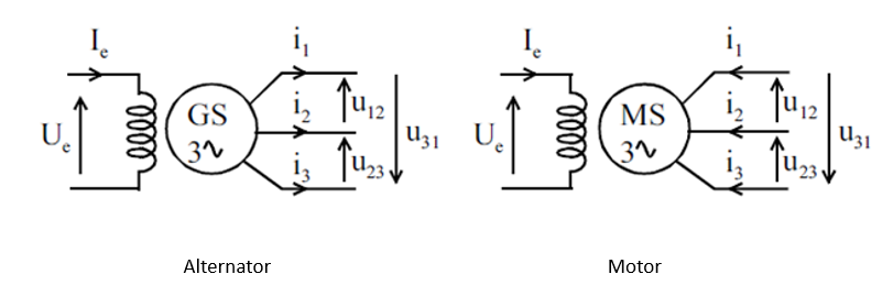
Figure 5: Sign convention in three-phase synchronous machines
1.6 Efficiency (powers and losses)
The useful or output power PU is defined as the electrical power supplied to the network while the absorbed power PA is the mechanical power absorbed by the alternator shaft.
Thus and taking into consideration the different losses, we construct the power tree of an alternator given by the following figure. where:
pJs : Stator copper losses (It occurs due to the input AC current and the armature winding resistance in the form of heat).
pFs : Stator iron losses (are losses that occur in the core or the iron parts of the synchronous motor due to the magnetic property of the material).
pJe : Rotor copper losses (are relatively smaller than stator copper losses due to the excitation current and rotor winding resistance).
pm : Mechanical losses (are made up of rotation and friction losses. They occur between the stationary and moving parts of the machine. These are constant losses as the rotor speed is constant in a synchronous motor).
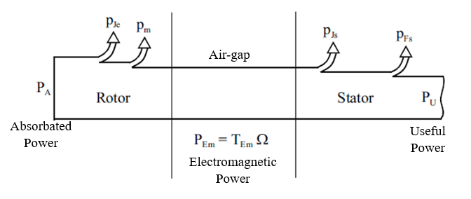
Figure 6: Powers tree
Ueff : Line voltage ; Ieff : Line current ; R1 : Phase-to-phase resistance of stator winding; Ue : Excitation voltage ; Ie : Excitation current ; TM : Machanical torque; TEM : Electromegnetic torque; PEM : Electromegnetic power.
The different powers and losses are given by:
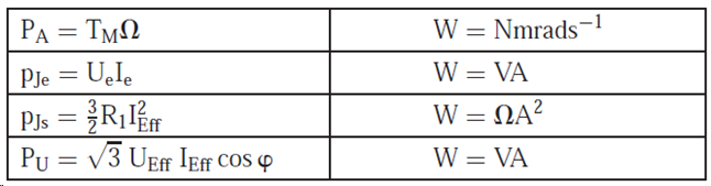
- Efficiency
The efficiency of the alternator is given by:
