
2. Model and characteristics (mathematical model)
2.1 Linearized model of a single phase referred to the stator
We refer the elements of the rotor to the stator by dividing them by m², m: being the transformation ratio per phase with an open rotor. We present the model of a phase referred to the stator in figure 5.
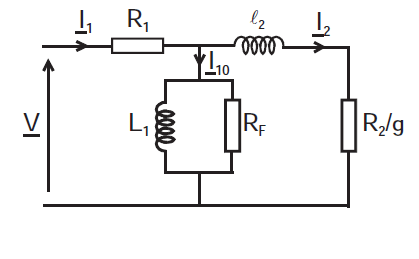
Figure 5: Model of a phase referred to the stator.
We define the different elements of the model as follows:
R1 : resistance of stator winding
L1 and Rf : iron core coil
l2 : leakage inductance
R2/g : fictitious resistance representing the transmitted power
R2 : resistance of the rotor referred to the stator
We take: PTr = PM + pJr, we show the resistance of the rotor referred to the stator by decomposing the fictitious resistance as follows:
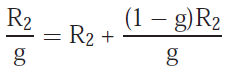
This makes it possible to separate the copper losses (dissipated in R2) from the mechanical power dissipated in (1-g)R2/g.
2.2 Determination of the model elements
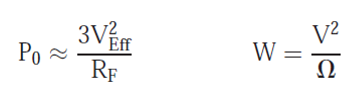
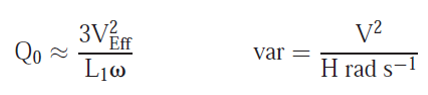
- A no-load test at synchronism makes it possible to determine RF and L1 by measuring:
- A no-load test with locked rotor under reduced voltage such that I1eff = I1Neff makes it possible to determine R2 and l2 by measuring:


- R2 is measured by a hot-line continuous test.
If we cannot measure the resistance R1 of a winding, we measure the resistance R between two phases. We recall that R = 2.R1 (in star coupling) and R = 2.R1/3 (in triangle coupling).
2.3 Electromagnetic torque characteristic
The curve of the electromagnetic torque (Tem or Cem) as a function of the motor speed n at constant voltage and frequency, is given in Figure 6.
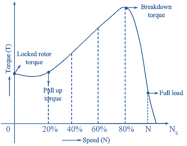
Figure 6: Electromagnetic torque characteristic
We notice that:
- The moment of the electromagnetic torque is non zero at start-up which means that the motor can start on its own.
- In the operating zone (between the breakdown torque point and the full load point), Tem = -an+b (which means that the variation is substantially linear).
2.4 Characteristic TU and I against speed n
In Figure 7, the curve of the torque and current intensity characteristic is plotted knowing that:
- Start-up current is high.
- The no-load current is not negligible.
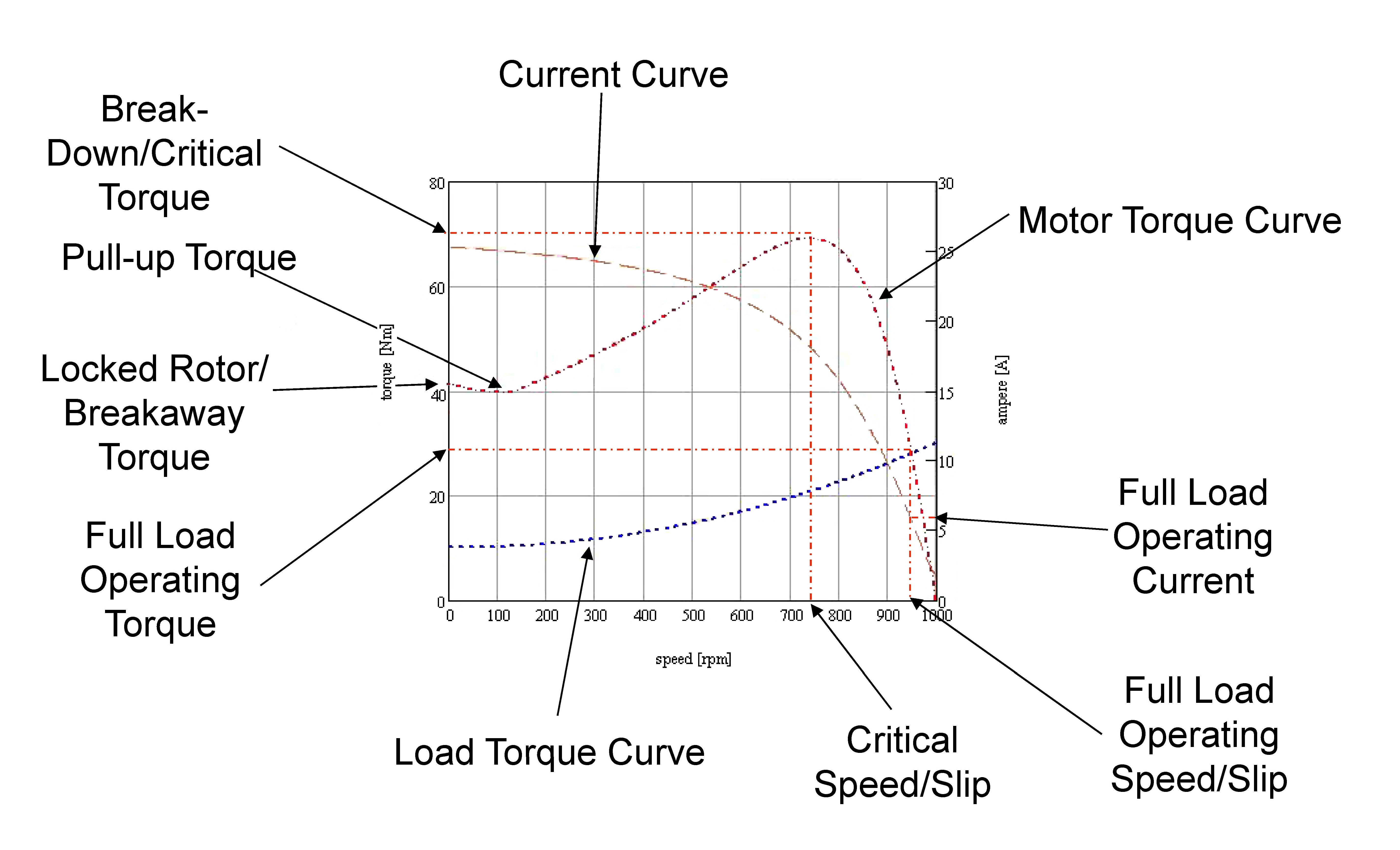
Figure 7: Curves of torque and current characteristics
3. Startup
At start-up operation, the fact that the current is high and the torque low implies that we should not start under load at rated (nominal) voltage, except for low power motors. To do this, we perform the startup:
- By actions on the stator, the current is reduced by reducing the voltage (star-delta coupling, dimmer, rheostat or starting coil, etc.). These techniques, also reducing starting torque, are generally used for starting without load.
- By acting on the rotor, the torque is increased: rheostat for wound rotor motors, and for others, creation of a motor with a double cage (two concentric cages) or with deep slots.
The current solution uses soft starters which act on the supply voltage and frequency.
4. Reversibility
Driven beyond synchronism (g < 0), the induction machine operates as a generator. It restores active power, but still consumes reactive power.
5. Braking
There are several possibilities depending on the type of load driven by the induction machine. Let us cite:
- Hypersynchronous braking. Based on Lenz's law, if the machine is driven beyond synchronism, the resulting rotating magnetic field (RMF) opposes this overspeed and the machine is braked. If the supply frequency is fixed, the speed of the rotating field is fixed, so this type of braking does not allow the machine to stop. On the other hand, fed by a power static converter providing the motor with a gradually decreasing frequency, the rotating field slows down and so does the rotor.
- Counter-current braking. It consists of inverting two power phases. In this case, the rotation direction of the rotating field reverses, and the motor brakes.
6. Single-phase induction motor
The starting torque being zero, a single-phase induction motor does not start alone, without special devices to create a rotating field such as the use of a capacitor or an auxiliary winding, Frager turns, etc. Compared to a three-phase motor, their efficiency is lower and their torque lower. They are mainly used in places not supplied with three-phase network (domestic installations) and for low-power driven machines.