
1. Presentation of direct current machines
1.1 Constitution
We consider the simple case of a bipolar machine (Figure 1).
- Inductor (stator)
This is the fixed part. Sometimes it is a permanent magnet, for small powers machines, but in general it is an electromagnet made up of two coils in series which, supplied with direct current, create two magnet poles: a north pole and a south pole. The magnetic field in the air gap is maximum in the pole axis, and zero in the direction perpendicular to this axis, called the neutral line.
- Armature (rotor)
This is the rotating part. It is a laminated ferromagnetic cylinder made up of slots in which conductors are distributed. It is a winding closed on itself. Positioned on the rotor, the collector, made up of conductive strips insulated from each other. The current is routed in the case of the motor, or recovered in the case of the generator, thanks to two carbon brushes rubbing on the collector.
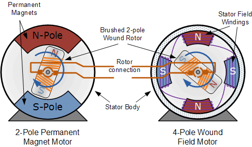
Figure 1: 2-pole and 4-pole DC machine
1.2 Reversibility
By moving a closed conductor in a magnetic field, a current (generator) is generated. Conversely, this same conductor carrying a current and placed in a magnetic field (motor) is subject to an electromagnetic force.
These two principles are present in a DC machines which is then perfectly reversible. We therefore have two main parts separated by an air gap:
- Inductor, which creates the magnetic field (excitation).
- Armature, which produces the current (generator), or which supplies the conductors with electric current (motor).
Important: the role of the collector is to change the direction of the current (by switching) in the conductors when crossing the neutral line (vertical line), thus allowing the Laplace forces to act in the same direction (see 1.4 Working principle).
The commutator and brushes are the weak point of a DC machine.
1.3 Nameplate, symbols and conventions
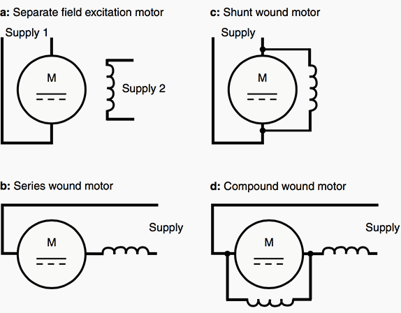
The nameplate indicates the rated values of the armature and inductor quantities, the excitation mode, the nominal speed and the useful mechanical power (case of the motor).
1.4 Working principle
The direct current (DC) machine uses the principle of electromagnetic induction. It is DC because it is powered by a direct current source such as a battery for example, which constitutes a current source which delivers a current always having the same direction. The main elements of a DC machine are shown in Figure 2.
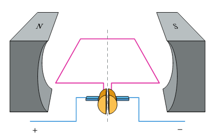
Figure 2: Main elements of a direct current machine
The direct current source is connected to the motor via two brushes. The brushes and wires used for the connection are shown in blue in the diagram. These brushes are curved to help maintain electrical contact with the commutator which is located between both brushes.
Around the coil there is a permanent magnet. This is shown in gray in the diagram. This magnet is often called a stator. This name indicates that this part of the motor remains stationary, unlike the coil which is rotating.
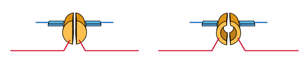
Figure 3: Types of switch or collector
We started by representing a DC machine with different colors to highlight the different elements. However, now that we have identified these different elements, it is perhaps more useful to represent the motor as in Figure 4.
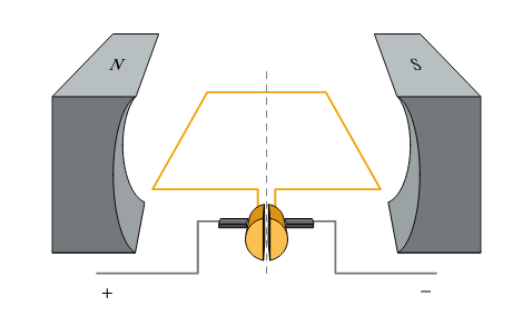
Figure 4: Representation of the DC motor
In this second version, the motor elements which are fixed (static) are represented in gray and those which can rotate in orange. Consider the path followed by the current. This path is shown in the diagram in Figure 5 with the coil in a horizontal position.
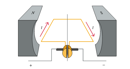
Figure 5: Current direction
Remember that by convention, current flows from the positive terminal to the negative terminal. So we have a current coming from the positive terminal.
The space between both halves of the switch prevents current from flowing directly to the negative terminal. However, because each half of the switch is connected to one end of the coil, current then flows through the coil. The current follows the turn of the coil until it reaches the other half of the commutator.
This second half of the switch is in contact with the brush connected to the negative terminal. The current can therefore reach the negative terminal by following this path, thus completing the circuit.
- Force exerted on a wire carrying a current in a magnetic field
Let's consider a wire of length L carrying a current of intensity I in a magnetic field B.
If the direction of the wire is perpendicular to the direction of the magnetic field, then the intensity of the force exerted on the wire is equal to:
F = B.I.L
The direction of the force is perpendicular to the current in the wire and the magnetic field and can be determined using the left-hand rule.
The force exerted on the wire is oriented in perpendicular to the direction of the current in the wire and the direction of the magnetic field. Let's then look at the direction of the current and the magnetic field.
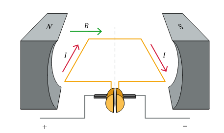
Figure 6: Magnetic field direction
The direction of currents flowing in both parts of the coil and which are perpendicular to the magnetic field are also indicated. Remember that only the current whose direction is perpendicular to the field will create a force. On the left side of the coil, current is directed “towards the screen”. On the right side, the current is directed towards us, “off screen”.
Let's focus on the left side of the coil. Here the current is directed “towards the screen”. The magnetic field is directed from left to right. We know that the force must be perpendicular to these two quantities, but there are still two possibilities: upwards or downwards.
To determine the direction of the force, we can use Fleming's left-hand rule.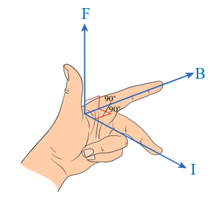
The principle of the rule represented visually is based on the following points:
- Place the index finger of the left hand in the direction of the magnetic field.
- Then, you must place the middle finger at an angle of 90° relative to the index finger, depending on the direction of the current.
- Then, you must place your thumb at an angle of 90° relative to the other two fingers, which will indicate the direction of the force exerted on the wire.
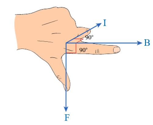
We see that the thumb is pointing downwards. This tells us that the force on the left side of the coil is directed downward.
We can apply the same process to the right side of the coil. In this case, the field is still pointing to the right, but the current is now directed towards us. We can easily check this using the left hand rule as the force on the right side of the coil is directed upwards.
The forces exerted on both sides of the coil therefore have the directions shown in the diagram in Figure 7. The diagram on the right is a top view where the direction of the current is indicated. The diagram on the right is a side view where the forces exerted are represented. In the diagram showing the side view, the direction of the current is also represented using the symbols ("x" towards the screen) and ("." off the screen).
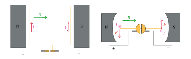
Figure 7: Direction of Laplace's forces.
It is important to note that the other two sides of the coil do not experience any force. This is because the direction of the current in these two sides is parallel to the direction of the magnetic field.
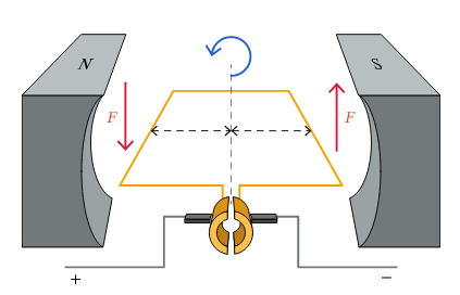
Figure 8: Rotation direction
The distance between the forces and the orientation axis has been highlighted in Figure 8 using the two black dotted arrows. Since the forces are not oriented along the axis, they will actually create torque on the coil.
In this case, the force on the left acts downward while the force on the right acts upward. As expected, the torque therefore turns the coil (with the commutator) in the direction indicated in the diagram in counterclockwise direction, according to the view that we have on this figure.
Until now, all our observations have been made in the case where the coil is located in a horizontal plane. However, we have just shown that the forces exerted on the coil so far create a torque which has the effect of making it rotate. This means we also need to consider what happens when the coil is oriented differently.
Let's look at the case where the coil has rotated through an angle less than 90° relative to the initial horizontal position considered. This is shown in Figure 9.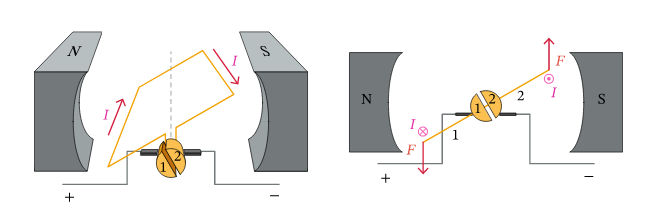
Figure 9: Coil rotation
We can see in Figure 9 that the commutator has rotated with the coil, but both halves of the commutator are still in electrical contact with the same brush. In other words, both halves of the switch have been identified with the numbers 1 and 2. So we can say that at this point, half n°1 of the switch is still in contact with the positive terminal and half n°2 of the switch is still in contact with the negative terminal.
This means that the electrical charges still move the same way in the circuit as when the coil was horizontal. Current flows in the same direction as before in the left and right sides of the coil.
Since the directions of the current are still the same and the direction of the magnetic field has not changed either, the forces exerted on both sides of the coil also have the same directions as before. Which means that, the force acting on the left side is directed downwards and the force acting on the right side is directed upwards.
As before, these forces are not directed along the rotation axis of the coil. They therefore create a torque. However, we can see from the diagram that the perpendicular distance between these forces and the axis of rotation is smaller than when the coil was horizontal. As these forces are exerted closer to the axis of rotation than before, the intensity of the torque created decreases.
As the coil rotates and approaches a 90° angle from the horizontal, the intensity of the torque exerted on the coil gradually decreases because the distance between the forces and the axis of rotation decreases.
Now consider what happens when the coil reaches a vertical position, which is shown in the diagram in Figure 10.
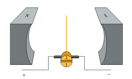
Figure 10: Coil in vertical position
We can see in Figure 10 that, in this position, whatever forces are exerted on the sides of the coil, they will be directed along the axis of rotation. No torque will therefore be created by these forces. In other words, when the coil is oriented vertically like this, there is no resulting torque. The coil continues to rotate only because it has a certain rotational moment of inertia; Since the coil was already moving counterclockwise, it will continue to rotate unless it encounters resistance.
There is another important point to note on this diagram: the position of the switch. Until now, half n°1 of the switch was always in electrical contact with the brush connected to the positive terminal. Likewise, half n°2 of the switch was still in contact with the brush connected to the negative terminal. The vertical position of the coil corresponds to a switching point. Beyond this point, half n°1 of the switch will contact the negative terminal, while half n°2 of the switch will contact the positive terminal.
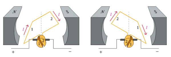
Figure 11: Change of coil position
The diagram on the left shows the coil before it reaches the vertical position. The sides of the coil are marked with the numbers 1 and 2 depending on which half of the switch they are connected to.
We can see that as the coil moves past the vertical position, the direction of current changes at the coil. Before reaching the vertical position, the current on side 1 was directed “towards the screen” while the current on side 2 was directed towards us, “off the screen”. But after passing the vertical position, the current on side 1 is directed “out of the screen” while the current on side 2 is directed “into the screen”.
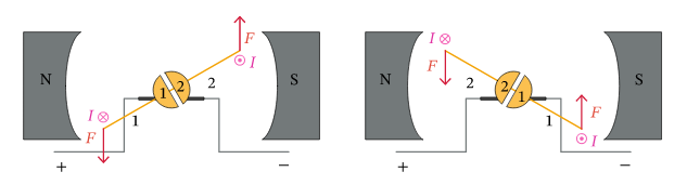
Figure 12: Direction of forces following coil position
We have again represented the coil in two positions, before and after the transition to the vertical position. In addition to the current directions in both sides of the coil, the forces exerted on both sides of the coil have also been shown. The directions of these forces can be checked using the left-hand rule.
Before reaching the vertical position (left diagram), the force exerted on side 1 was directed downward and the force exerted on side 2 was directed upward. We saw previously that the force exerted on the left side of the coil was directed downward and the force exerted on the right side was directed upward.
Looking at the diagram on the right, we see that after moving from the vertical position, the force exerted on the left side of the coil is still directed downward and the force exerted on the right side is still directed upward . However, side 1 is now the right side and side 2 is the left side. Because the direction of current through the coil has changed, the direction of the forces acting on both sides of the coil has also changed.