
2. Study of a three-phase alternator
2.1 Characteristics of a three-phase alternator
- Voltage across windings
At the terminals of each winding, the alternator provides balanced three-phase voltages:
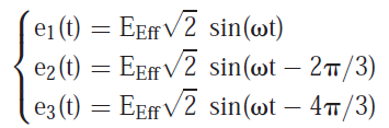
- Electromotive force across the winding
The RMS value of the e.m.f across a winding is given by :
Eeff = K . N . f . Фmax
Eeff : RMS value of the no-load e.m.f. across the winding.
N : number of active conductors of the winding.
f : frequency of the induced voltage in Hz (f = p . n) with n : the rotation speed in rev/s.
Фmax : maximum flux for a turn (i.e. two conductors) in Wb. The flux being with sinusoidal distribution is given by:
φ(t) = Фmax cos(ωt)
K : Kapp coefficient which depends on the construction of the machine.
- No-load characteristic (internal characteristic)
The operating point P is located in the curved point of the saturation characteristic shown in Figure 7.
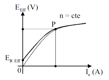
Figure 7: No-load characteristic
Because of the hysteresis phenomenon, the load characteristic starts from a remanent e.m.f. which is thus taken into consideration.
- Autonomous alternator
Autonomy: an alternator is called autonomous if it supplies a load without coupling (case of generators). On the other hand, it is no longer autonomous if it is coupled to the electric network.
Armature reaction: when the alternator delivers power, the armature creates a rotating magnetic field which modifies the useful flux, thus modifying the e.m.f. This is the armature reaction. The load e.m.f. is thus different from the no-load e.m.f., created by the rotor pole.
-Load characteristic (external characteristic)
The armature reaction modifies the e.m.f. depending on the load. In this case, the excitation current must be modified to stabilize the voltage. The load characteristic thus obtained is given in Figure 8.
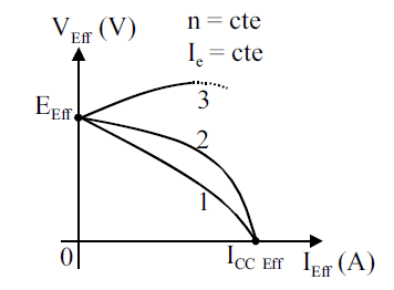
Figure 8: Load characteristic
The load characteristic of the Figure 8 is considered for the following cases: 1: Inductive load. 2: Resistive load. 3: Capacitive load.
2.2 Parallel operation of three phase alternators
When number of alternators are connected to same bus-bars, they are called to be connected in parallel.
Such practice is considered necessary for the following reasons:
-Physical size: The output power of modern power stations is so high that it is difficult to build a single unit of that capacity.
-Reliability or continuity of service: Several small units are more reliable than a single large unit because if one unit fails, the continuity of supply can be maintained by operating the other units.
-Repair and maintenance: Repair and maintenance of a unit is more convenient and economical if a large number of smaller units are installed at the power station.
-Size and cost of stand-by unit: Since each unit is of smaller size, the cost of stand by unit is small.
-Extension of power plant: The additional unit can be installed as and when the load demand increases.
-Operating efficiency: Moreover, the load on the power station varies greatly both during day and night as well as during the different seasons. Thus, the number of units operating at a particular time can be varied depending upon the load at that time. This keeps the machines loaded upto their rated capacity and hence results in increasing the efficiency of operation as the efficiency of an electrical machine is maximum at or near rated capacity.
2.2.1 Requirements for parallel operation of alternators
The requirements for the parallel operation of alternators are:
1. Output voltage rating: The output voltage rating of all the alternators must be the same
2. Output frequency: The rated speed of all the machines should be such that they produce the same frequency.
3. Output wave shape: The output wave form of all the alternators must be the same, although their kVA rating may be different.
4. Speed-load characteristics: The drooping speed-load characteristics of the prime-movers of the alternators should be the same so that alternators share the load in their proportion as per their output (kVA) rating.
5. Impedance triangles: The impedance triangles of the alternators should be identical for successful parallel operation.
2.2.2 Synchronising alternators
The procedure of connecting an alternator in parallel with another or with common bus-bars to which a number of alternators are already connected, is called synchronising of alternators.
2.2.3 Conditions for proper synchronising
For proper alternator synchronising, the following conditions must be fulfilled:
1. The terminal voltage of the incoming alternator must be equal to that of the bus-bar voltage.
2. The voltage of the incoming alternator should be in phase opposition to the bus-bar voltage. This implies that there will be no circuiting current between the windings of the alternators already connected to bus-bars and the incoming alternator.
3. The speed of the incoming alternator must be such that its frequency is equal to that of bus-bar frequency.
4. In case of three-phase alternators, the phase of the incoming alternator must be identical with the phase of the bus-bars. In other words, the phase sequence of the incoming alternator must be same as that of the bus-bars.
2.3 Equivalent model of the machine reffered to the stator
- Behn-Eschenburg model or synchronous reactance
Using the mesh equation, we obtain the model of a single phase shown in Figure 9.
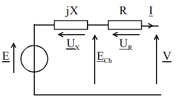
Figure 9: A single phase model
The equation resulting from this model is given by:
E = V + UX + UR
We then construct the Fresnel diagram according to the previous model. This vector diagram (also called phasor diagram) is given in Figure 10.
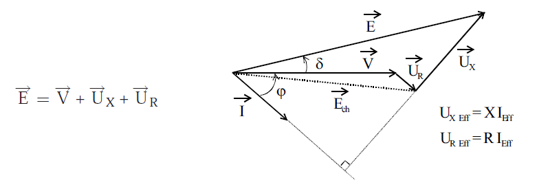
Figure 10: Fresnel or phasor diagram.
Veff : Voltage of a single winding (V)
Ieff : current in a single winding (A)
Eeff : No-load e.m.f (V)
Ech : Load e.m.f (V)
R : Resistance of a single winding (Ω)
X : Synchronous reactance (Ω) with: X = L.w
L : inductance which takes into consideration all windings and leakages (H)
Important:
- In general, the resistance R can be neglected from the equivalent model since R << X. In this case, the load e.m.f. mentionned as Ech which is equal to the voltage of a single winding V.
- The angle δ is an electrical angle called: internal offset angle. This angle represents the offset of the rotor between the operating modes: "No-load operation" and "load operation" of the machine.
Therefore, we can write that:
* In an alternator mode, the rotor advances by an angle δ = p.θ.
* In a motor operation, the rotor moves back by an angle δ = p.θ.
where : θ is the mechanical angle.
- Determination of model elements
The resistance R is determined by a hot-line continuous measurement. Then and from the "no-load" and "short circuit" characteristics ICCeff = f(Ie), we find for a given value of the excitation current Ie1: ICC1eff and E1eff.
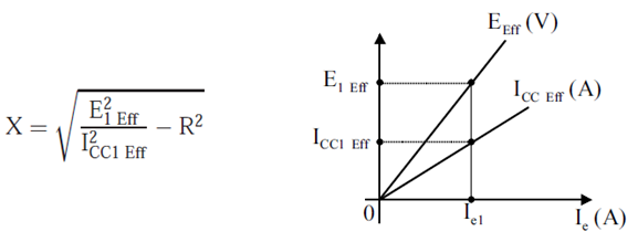
Figure 11: “No load” and “short circuit” characteristics.
If we cannot measure R of the winding, we can always measure R1 between 2 phases. It should be noted that with a star coupling: R1 = 2R whereas R1 = 2R/3 in triangle coupling.
- Validity and limitation of the Behn-Eschenburg model
The Behn-Eschenburg model is used in the case of an unsaturated cylindrical-pole rotor alternator. In this specific case, the synchronous reactance X is constant.
If the alternator is barely saturated, we can linearize the no-load characteristic of the alternator, thus confusing the operating points P and P' represented in Figure 12.
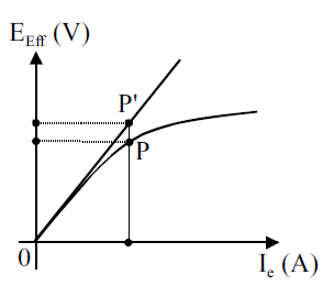
Figure 12: “No-load” characteristics of a barely saturated alternator.
If, on the other hand, the saturation is important, we can still use the Behn-Eschenburg model but the synchronous reactance X is no longer constant and must be determined for each operating point.
Finally, the Behn-Eschenburg model is certainly the simplest but the least precise model. There is a model based on the Poitier diagram which takes saturation into account. Also, Blondel's model is intended for the study of alternators with salient poles rotor.