
3. Armature reaction of synchronous machines
Assuming that the induced voltages and the fluxes through the turns are sinusoidal quantities of the same frequency, we can associate vectors to these machine quantities in Fresnel diagram (or in the complex plane).
For No-load operation, we use the generator convention (where the inductor flux ФJ leads the e.m.f. by an angle of π/2 rad) and in the motor convention (where the flux ФJ lags the e.m.f. by an angle of π/2 rad) . This is shown in Figure 13.
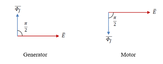
Figure 13: Position of the e.m.f. versus the inductor flux.
When the machine is operating under rated load, the currents circulating in the stator windings create an additional field rotating at the same speed as that generated by the rotor and superposed one on the other.
In the case of synchronous machines, the position of the stator field depends on the phase shift between currents and voltages. This causes significant variations in the resulting e.m.f. as the load changes.
- Case of a pure capacitive load (fig. 14.a), the armature reaction flux ФI is in the same direction as the inductor flux ФJ.
- Case of a pure inductive load (fig. 14.b), the armature reaction flux ФI is on the same axis as the inductor flux ФJ but in the opposite direction.
- Case of a pure resistive load (fig. 14.c), the armature reaction flux ФI is in front quadrature (leading of an angle of π/2 rad) with respect to the inductor flux ФJ.
- Case of a random load (fig. 14.d), the armature reaction flux ФI is ahead by an angle of Ψ + π/2 with respect to the inductor flux ФJ. In this case, the armature flux ФI is decomposed into two components: a longitudinal component ФI ln of the same axis as the inductor flux ФJ and a transverse component ФI tr in front quadrature with respect to the inductor flux ФJ.
The angle Ψ is negative when the load is capacitive and is positive when the load is inductive. The different armature reactions are given in Figure 14.
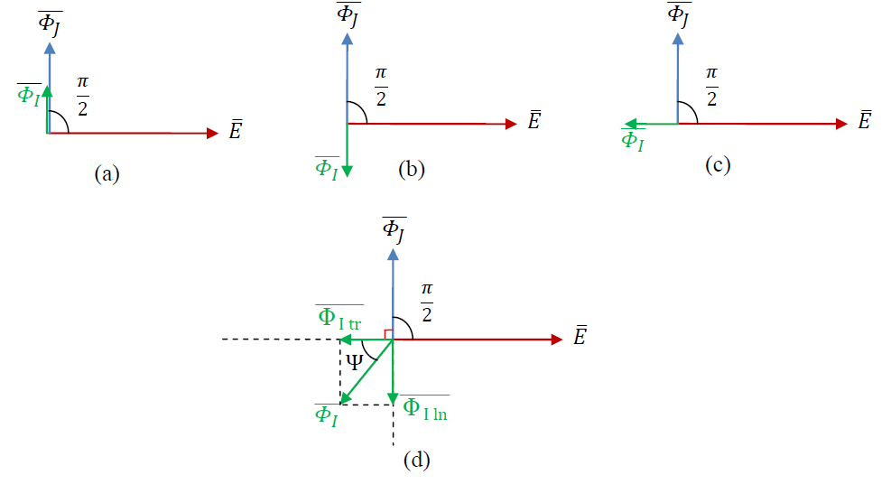
Figure 14: Position of the e.m.f. versus the armature flux for a random load.
In all cases, it is the resulting flux Фr (the vector sum of the inductor flux ФJ and the armature reaction flux ФI) which induces a resulting e.m.f. called Er different from the no-load e.m.f. noted E when the inductor flux acted alone. This new resulting e.m.f. is given by:
Er = k . N . f . Фr
- Case of a salient pole machine
In the case of a synchronous machine with salient poles, the path of the armature reaction flux ФI depends on the position of the field poles.
Along the transverse axis, the effect of the armature reaction flux is less significant because the air gap is larger. Thus, the transverse reaction armature flux component named ФI tr no longer acts completely. Only a part of this component (multiplied by a reducing coefficient k') is added to the longitudinal component to form the resulting flux Фr. This modification of the armature reaction flux ФI in the case of a rotor with salient poles is given in figure 15.e.
The resulting flux Фr as well as the resulting e.m.f. "Er" are given in Figure 15 with an angle of π/2 in advance of the resulting flux versus the resulting e.m.f. (using generator convention).
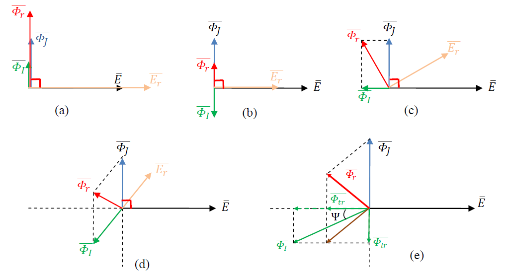
Figure 15: Position of the resulting e.m.f. versus the resulting flux.