
4. Poitier diagram
If the alternator is saturated, we use the Poitier method. In this case, we compose the rotating magnetomotive forces due to the inductor (the rotor) fR and due to the armature (the stator) fS phase shifted by the angle ψ + π/2 where: ψ = δ + φ.
Therefore, the resulting magnetomotive force is given by:
fr = fR + fS
By dividing this expression by the number of turns of the direct current inductor, we obtain:
Ie = fR/N : inductor current (direct).
Ier = fr/N : inductor current resulting from both the inductor and the armature.
α.I = fS/N : direct current equivalent in the armature.
α : equivalence coefficient allowing to calculate the armature current referred to the inductor.
The load e.m.f. "Er" is given by the no-load characteristic for the value Ier of the resulting excitation current.
- Construction of the Poitier diagram
Starting from V, I, φ; we construct Er. We read Ier on the no-load characteristic and we plot it on the diagram where Ier leads Er by an angle of 90° (generator convention). We then construct the current α.I in phase with the armature current I then we obtain Ie.
To complete the diagram, we place E on the same diagram where E lags Ie by an angle of 90° (generator convention) which makes the angle ψ appear.
Using the equivalent model of a single phase of the three-phase alternator, the Poitier diagram is given in figure 16.
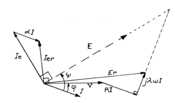
Figure 16: Poitier diagram of the synchronous machine
The leakage inductance λ is included in the synchronous inductance L.
5. Kapp diagram (Diagram of the two reactances)
Also called the two reactances diagram, it is used for a synchronous machine with salient poles in linear (unsaturated) state where the e.m.f. is proportional to the excitation currents (the saturation of the magnetic circuit is neglected).
We first construct the resulting e.m.f. "Er" which is proportional to the excitation current Ier.
Since the machine has salient pole rotor, the armature reaction is illustrated along two axes: longitudinal and transverse and thus, the resulting e.m.f. can also be represented along two axes:
* The resulting e.m.f along the transverse axis Etr created by the transverse armature reaction flux (Фtr) which lags the longitudinal armature flux (Фlr) by an angle of 90°. However, Фtr is multiplied by a reduction coefficient k', hence: Etr depends on (k'.α.I.cosψ).
We draw the Kapp diagram by defining two reactances:
Xl : longitudinal synchronous reactance.
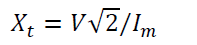
Xt : transverse synchronous reactance.
The Kapp diagram is given in Figure 17. The no-load e.m.f. is thus obtained from this diagram.
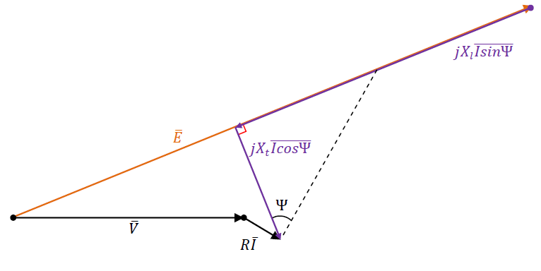
Figure 17: Kapp diagram.
The Kapp diagram is called a two-synchronous reactance diagram. If the reduction coefficient k' is equal to 1 (case of a synchronous machine with cylindrical poles rotor), this diagram become equivalent to the synchronous reactance diagram (Behn-Eschenburg diagram with a single reactance).
- Determination of synchronous reactances
The determination of both synchronous reactances is done by the slip test. Indeed, the slip test is a simple no-load test, which is used to determine the direct-axis and quadrature-axis synchronous reactances of a salient-pole synchronous machine. In this test, a small voltage at rated frequency is applied to the three-phase stator winding of the synchronous machine. The field winding is unexcited and left open circuited.
In this test, the stator winding is supplied by a balanced three-phase source of RMS value V and rated frequency f.
The rotor circuit being open, the machine is driven in the direction of the rotating field at a speed very close to the synchronous speed.
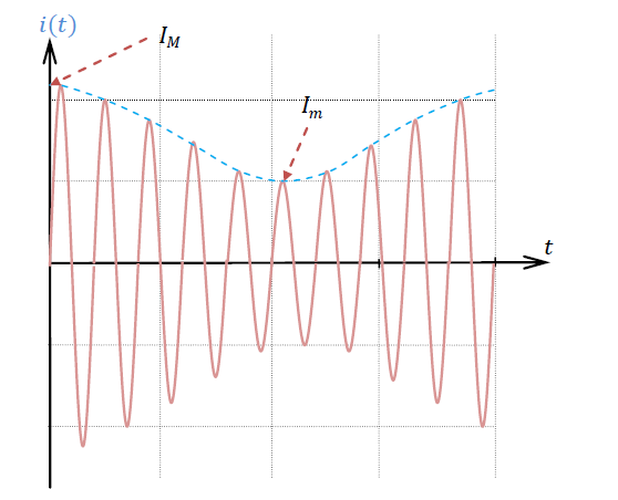
Figure 18: Current waveform obtained during the slip test.
When the rotating field is on the inductor poles, the value of the current gives the direct-axis synchronous reactance:
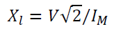
When the rotating field is on the interpolar axis, the value of the current gives the quadrature-axis synchronous reactance:
6. Blondel Diagram
The Blondel diagram is used for a synchronous machine with salient poles taking into consideration the saturation of the magnetic circuit. In this diagram, Blondel assumes that the transverse e.m.f "Etr" is proportional to the current creating this e.m.f (k'.α.I.cosψ). In fact, Blondel's diagram neglects saturation along the transverse axis.
We plot the resulting e.m.f. "Er" first. Then, we draw the e.m.f. "Etr" and "Elr" as in the case of the Kapp diagram.
According to the no-load characteristic, we read the value of the longitudinal inductor current Jlr. To find the inductor current J, we add to Jlr the current (α.I.sinψ) necessary to compensate the longitudinal reaction.
J = Jlr + α.I.sinψ
The Blondel diagram is given in figure 19.
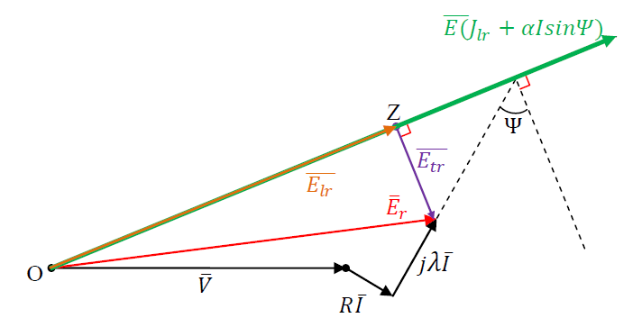
Figure 19: The resulting e.m.f. using the Blondel diagram.
- Determination of Blondel diagram parameters
The parameter α is deduced in the same way as the Poitier diagram while the determination of both synchronous reactances is based on the slip test as for the Kapp diagram (explained above).