
Presentation of induction machines
1.1 Constitution
Induction machines are made up of two parts separated by an air gap:
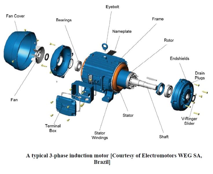
- Stator or inductor
It is the fixed part, in the form of a laminated ferromagnetic carcass comprising a three-phase 2p poles winding when is supplied by balanced three-phase currents, generates a rotating magnetic field (RMF) with quasi-sinusoidal distribution similar to the armature of a synchronous machine supplied by a three-phase system of angular frequency ω = 2πf [rad/s].
The windings can be connected in star or triangle.
Most often, stators are designed with p = 2, i.e. a synchronism speed of 1500 rpm.
- Rotor or armature
This is the rotating part. There are two types of rotors :
(1) wound-rotors (also called ring-rotor) made of a winding similar to that of the stator supplied via rings and brushes and can be connected to an external rheostat (used as statrting resistor) ;
(2) squirrel-cage rotors made of short-circuited conductive bars. Cage rotors are more robust and less expensive.
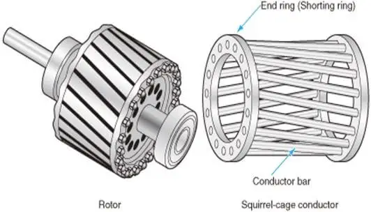
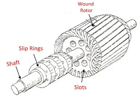
Figure 1: Rotor types of induction machines
1.2 Symbols and conventions
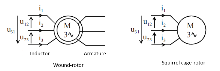
Figure 2: Symbols of three-phase induction motors
1.3 Working principle
The stator, being supplied by a three-phase system of voltages at the angular frequency ω, creates a rotating field (Ferraris theorem) at the synchronism speed Ωs = ωs/p (rad/s). This field induces a three-phase system of currents in the rotor, which creates a rotating field at the same speed Ωs. The resulting field (of the stator and rotor) and the three-phase currents generate an electromagnetic torque which tends, due to Lenz's law, to reduce the cause which gave rise to the currents by driving the rotor at a speed slightly lower than the synchronism speed; that is, the relative rotation of the magnetic field with respect to the rotor.
(1) drive the rotor following the sliding field if Ω < Ωs, and the machine then operates as an induction motor.
(2) brake the rotor if Ω > Ωs, and the machine then operates as an induction generator.
- Lenz's law
Lenz's law states that "An induced electromotive force generates a current that induces a counter magnetic field that opposes the magnetic field generating the current".
1.4 Motor slip
The rotation of the machine is characterized by the relative difference in speed between both rotor speed and synchronism speed (that of the sliding field). We note s (or sometimes g in French for: glissement) the "sliding of the rotor" versus the sliding magnetic field:
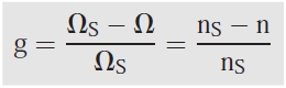
Ωs, ns : respectively, synchronism speed in rad/s or rpm.
Ω, n : respectively, rotor speed in rad/s or rpm.
The motor slip is between 0 and 1. If the motor slip is close to 0 we can say that the induction motor is running at no load operation mode; whereas if the motor slip is equal to 1, the motor is stopped.
1.5 Nameplate
The nameplate of a three-phase induction motor is given by the following figure:
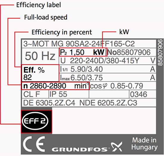
Figure 3: Nameplate
On this plaque we can read:
– The lowest voltage is the rated voltage supported by a stator single winding (here ~230 V). This data makes it possible to define the winding connection (coupling) according to the electric network available. A terminal box allows the coupling to be made.
– The lowest current is the rated line current in the case of star coupling.
– Also indicated, for nominal operation, the rated values of the useful power, the power factor, the rotor speed and the frequency.
With a 230/400 V network, we will connect the stator in triangle while with a 400/690 V network, we will couple it in a star-connection.
1.6 Efficiency
We define the useful power PU as the mechanical power supplied to the load via the motor shaft while the absorbed power PA is the electrical power absorbed by the stator windings.
Thus and taking into consideration the different losses, we construct the power tree of an induction motor given in Figure 4. where:
pJs : Stator copper losses.
pFs : Stator iron losses.
pJr : Rotor copper losses.
pm : Mechanical losses.
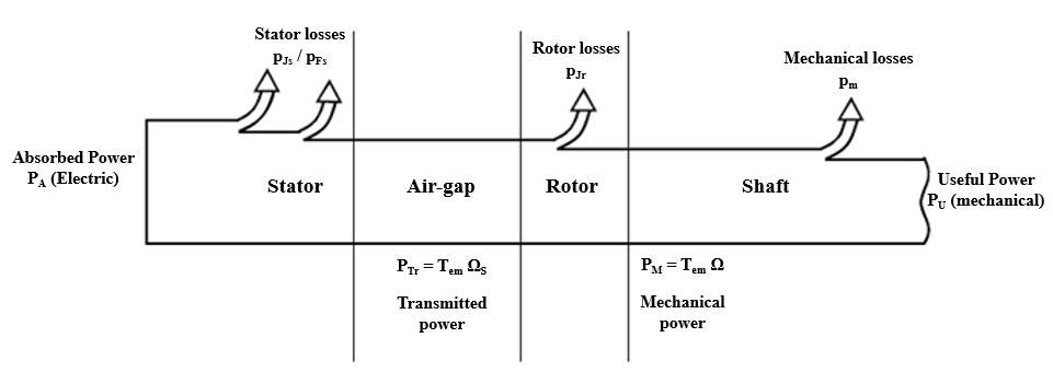
Figure 4: Power tree
PTr: is the transmitted power from the stator to the rotor (Tem or Cem: represents the electromagnetic torque. TU or CU: the useful torque).
PM: is the mechanical power at the motor shaft.
R: resistance between two stator phase wires.
The rotor iron losses pFr are negligible because the frequency fR of the rotor currents is generally low (fR = g . f).The different powers and losses are given by:
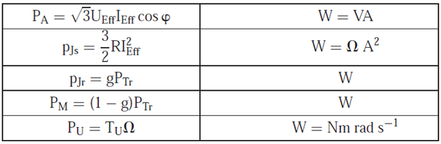
- Motor efficiency
The efficiency of induction motors is given by:
