
3. Rotating magnetic field
The magnetic field induced in an electric machine is illustrated by the following figure:
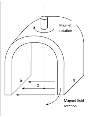
The movements of a needle with those of the magnet are synchronized at the same speed Ωs hence the name synchronism speed.
The principle of alternating current motors lies in the establishment of a rotating magnetic field produced by alternating voltages. The circulation of a current in a coil creates a magnetic field B. This field is in the axis of the coil and its direction and its intensity are a function of the current I. Therefore, the magnetic field is considered as a vector quantity.
In the case of alternating current, the magnetic field changes in direction of the current frequency.
If two coils are placed close to each other, the resulting magnetic field is the vector sum of both magnetic fields (resultant).
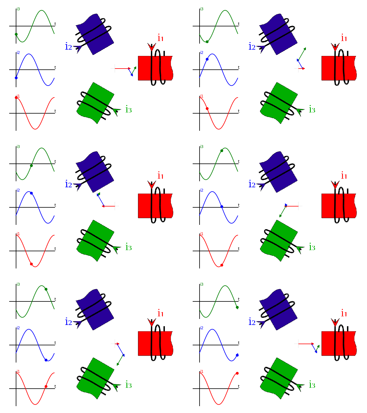
Magnetic field in the air gap of rotating machines
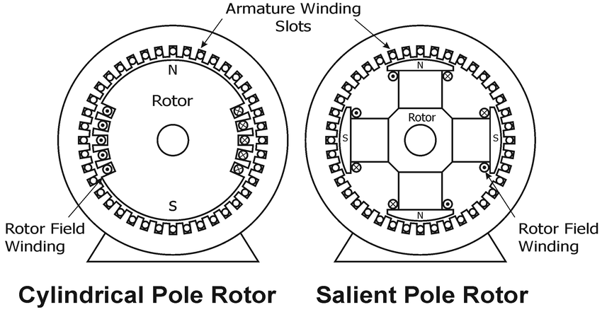
There are two types of rotor windings: winding arranged on cylindrical poles and winding arranged on salient poles as shown in the following figure.
In machines with p pairs of poles, a spatial period is reproduced p times in one revolution. Therefore, the spatial period is equal to 2π/p.
Example:
In the following figure, the winding of a machine with 2 pairs of poles (4 poles) and 20 conductors is shown.
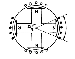
A mechanical angle 2π/p corresponds to a period of electromagnetic quantities.
Example:
For p = 2, we rotate a 4-pole magnet in the center of the winding. The period of the signal across the winding corresponds to 1/2 turn, i.e.: 2π/2 = π.
We therefore define the notion of electrical angle 2π electrical (1 period) which corresponds to 2π/p mechanical.
So, we find:
θelec = p . θmec
Magnetic field created by the windings of three-phase machines
The stator has three coils offset from each other by an electric angle of 2π/3. So, geometrically offset by a mechanical angle is 2π/3p.
The three-phase winding at the stator is thus made up of three identical single-phase windings placed at the stator, whose axes E1, E2 and E3 are offset by 2π/3p (see previous figure), and supplied by a three-phase system of currents:
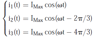
Let's consider a three-phase winding with four poles (p = 2).
Each winding creates an excitation with sinusoidal distribution, proportional to the current. Therefore, the three coils create a magnetic field in the sinusoidally distributed air gap rotating at the angular speed Ω = ω/p. This rotating magnetic field (RMF) has the expression (see the Support video: The Rotating Magnetic Field (RMF) of a Three Phase Winding):
B1(θ,t) = Bm cos(pθ) cos(ωt)
B2(θ,t) = Bm cos(pθ - 2π/3) cos(ωt - 2π/3)
B1(θ,t) = Bm cos(pθ - 4π/3) cos(ωt - 4π/3)
Ferraris theorem
A symmetrical and multipolar (p pairs of poles) polyphase (q phases) winding, supplied by a balanced polyphase system of currents, creates in the air gap a multipolar field with sinusoidal distribution, rotating at the synchronism speed Ω = ω/p.
Rotating field speed
By applying Ferraris theorem at a frequency of 50 Hz, we obtain:
p = 1 ==> 1 electric period ==> 1 revolution ==> 3000 rpm
p = 2 ==> 1 electric period ==> 1/2 revolution ==> 1500 rpm
p = 3 ==> 1 electric period ==> 1/3 revolution ==> 1000 rpm
p = 4 ==> 1 electric period ==> 1/4 revolution ==> 750 rpm
4. Armature Winding
In the large synchronous machines, stationary part is the armature. On the inner periphery of the stator core, number of slots (mostly open parallel sided slots) are provided. In these slots armature winding is placed.
4.1 Types of Armature Winding
Various types of winding schemes can be adopted to wound the armature of an alternator, a few of them are given below:
4.1.1. Single-phase and poly-phase windings: When only one winding is placed on the armature and only one emf is obtained at the output, winding is called single-phase winding.
When more than one windings are placed on the armature and emfs induced are more than one, displaced from each other by some angle, the winding is called poly-phase winding. Mostly three-phase winding is provided on the armature.
4.1.2. Concentrated and distributed windings: When one slot per pole or slots equal to the number of poles are employed, the windings thus obtained are called concentrated windings. Such windings give maximum induced emfs for given number of conductors but the wave form of induced emf is not exactly sinusoidal.
When number of slots per poles are more than one, the windings thus obtained are called distributed windings. Such windings give slightly less than maximum induced emf for a given number of conductors but the wave form of induced emf is more sinusoidal.
4.1.3. Single layer and double layer windings: When only one coil side is placed in a slot, the winding is called single layer winding. However, when two coil sides are placed in one slot, one over the other, the winding is called double layer winding.
4.1.4. Full pitched and short pitched windings: When the two coil sides of the same coil are 180 electrical degrees apart, the winding is called full pitch winding. When the two sides of the same coil are less than 180 electrical degrees apart, the winding is called short pitch winding.
The emf induced in each coil is maximum with full pitch winding scheme is employed whereas emf induced in the short pitch winding is less than that. However, short pitch winding is preferred over full pitch winding because of the following reasons:
-It decreases the length at the end-connections and thus amount of copper required is saved.
-It reduces the slot reactance and thus improves the wave shape of the generated emf, i.e., the generated emf can be made to approximately sinusoidal more easily by properly chording the winding.
-It reduces or eliminates distorting harmonics in the wave form of generated emf.
The only disadvantage of short pitch winding is that a few more turns are used to obtain the same voltage as it would be induced in full pitch winding.
4.1.5. Concentric (or spiral), Lap and Wave windings: When each group of coils under a pole is arranged into a sort of concentric shape i.e., when the current flow is traced through one such properly connected set of coils that the conductors seem to form a spiral around a portion of the core, the winding is called concentric or chain or spiral winding. This type of winding scheme is preferred for large diameter, low speed synchronous machines.
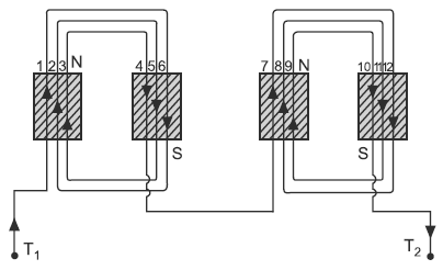
Concentric winding
In the alternators, the lap and wave windings give the same emf as long as the other conditions are the same. In case of lap winding, coils or coil sides overlap the other consecutively and connections are made. Whereas in wave winding, the coils are always forward connected. The connections of a lap winding are simpler to that of the wave winding, therefore lap winding is exclusively used.
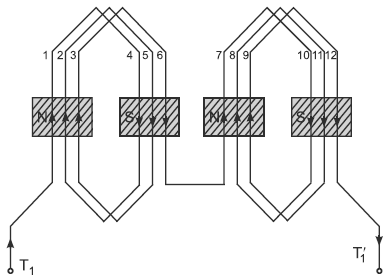
Lap winding
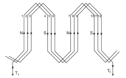
Wave winding